Topic: NASA-LSP-2026-014: In-Situ Resource Utilization for Lunar Surface Construction
Contract: NNX25-LR-0042 (Phase I) → Phase II Proposal
Title: Lunar Regolith Sintering for In-Situ Habitat Printing
Phase: SBIR/STTR Phase II — 12 months, $1,500,000 total
Principal Investigator: Principal Investigator (Example Institute of Selenology)
Co-Investigator: Co-Investigator (Example Institute of Selenology)
Submission Date: 2026-04-15
Proposal Type: Direct-to-Phase-II
1.0 Introduction
The cost of launching mass to the lunar surface is the dominant constraint on every long-duration mission profile. Conventional habitat designs treat structural materials as cargo and budget every kilogram against transit fuel; under that model, surface infrastructure scales linearly with launch tonnage and a single permanent outpost remains an order of magnitude beyond program affordability.
This proposal generalizes our Phase I prototype into an operational in-situ resource utilization (ISRU) platform that prints load-bearing structures directly from lunar regolith. The Phase I effort (Aug 2025–Feb 2026, $250,000) sintered JSC-1A regolith simulant into compression-test coupons reaching 27.4 MPa — comparable to a low-grade masonry block — at a print resolution of 220 µm [1]. Phase I demonstrated that the sinter profile, gantry kinematics, and dust-tolerant powder bed all work as an integrated system on Earth.
Phase II (12 months, $1,500,000 total) carries the prototype from terrestrial vacuum-chamber operation to a flight-qualifiable subsystem rated for the lunar thermal and radiation environment. See Section 4.0 for the full milestone schedule.
2.0 Specific Aims
2.1 Aim 1 — Vacuum-Compatible Sinter Profile
Develop and characterize a sinter profile that produces structurally sound parts under lunar surface conditions (10-9 Torr, diurnal cycling between -173 °C and 117 °C). Phase I validated the profile at 1 atm in a glovebox; Phase II re-runs the parameter sweep in a thermal-vacuum chamber and quantifies the gap.
Hypothesis: a stepped 1380 °C → 1420 °C profile compensates for reduced convective heat loss in vacuum and yields ≥25 MPa compressive strength on JSC-1A coupons.
2.2 Aim 2 — Dust-Mitigation Recoater
Replace the Phase I roller recoater with a dust-tolerant blade mechanism qualified for the abrasive fines characteristic of mature lunar regolith. Failure mode analysis of Phase I prototypes showed recoater binding as the leading defect source; this aim eliminates that failure mode.
2.3 Aim 3 — Closed-Loop Quality Control
Integrate inline thermal-imaging-based defect detection into the print path, with a per-layer go/no-go decision that pauses printing on anomaly. Targets ≥95% defect-detection sensitivity at <2% false positive rate, validated against ground-truth metallography.
3.0 Technical Approach
3.1 System Architecture
The Phase II prototype is a five-subsystem integrated printer. Figure 1 shows the layout; descriptions of each subsystem follow.
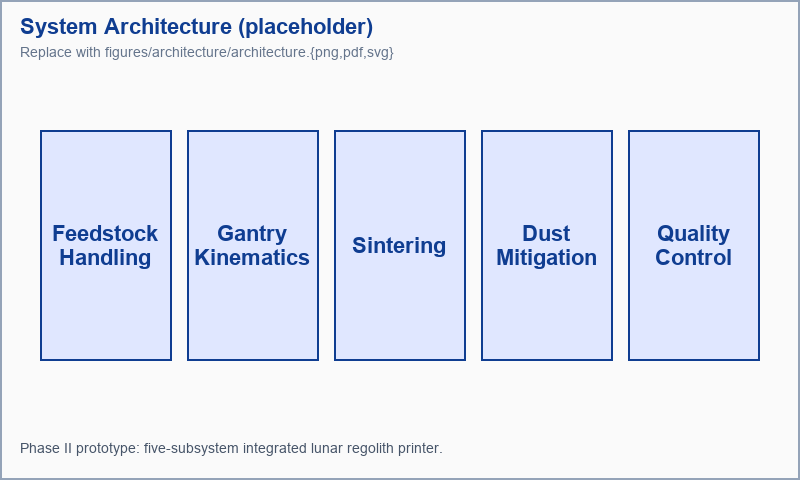
Feedstock handling. A vibratory hopper meters JSC-1A simulant into a heated buffer that drives off adsorbed water before the powder reaches the print bed. Lunar-relevant grain size distributions (median 70 µm, with 10% sub-20 µm fines) drive the hopper geometry.
Gantry kinematics. A three-axis CoreXY gantry positions the sinter head over the 220 µm-resolution print bed. The gantry is rated for thermal-vacuum operation and uses graphite bushings rather than oil-lubricated bearings to survive the sub-Torr environment.
Sintering. A 250 W diode laser delivers the focused thermal input to the powder bed. The Phase I stepped profile is documented in Aim 1; we extend that profile in Aim 2 for the vacuum-chamber gap.
Dust mitigation. The recoater is a blade-edge design with a purge-gas knife (low-flow, recycled) that re-fluidizes settled fines. This subsystem is the focus of Aim 2.
Quality control. An inline 8 µm thermal camera images each layer post-sinter; layer-level features feed a small CNN classifier trained against metallography ground truth. Aim 3 develops this classifier.
3.2 Scientific Foundations
The approach builds on three demonstrated foundations:
- Solid-state sintering kinetics for binary basaltic glass systems are well-characterized in the powder-metallurgy literature [2]. Our Phase I profile leverages the iron-rich phase of JSC-1A as a sintering aid.
- Vacuum-compatible drive trains at the scale of a desktop gantry have flight heritage from cubesat reaction wheel assemblies.
- Inline thermal-imaging defect detection is a mature technique in industrial metal AM [3]; we adapt the published feature pipeline rather than inventing a new one.
3.3 Key Technical Risks
| Risk | Likelihood | Impact | Mitigation |
|---|---|---|---|
| Coupon strength <25 MPa in vacuum | Medium | High | Stepped profile (Aim 1); fall-back binder-jet path |
| Recoater binding on fines | High | Medium | Blade redesign + purge knife (Aim 2) |
| QC false-positive rate too high | Low | Low | Larger training set, ensemble classifier |
A more detailed five-row register lives in tables/risk_register.tsv and is rendered below in Section 4.2.
4.0 Project Plan
4.1 Milestone Schedule
Phase II is organized as six bimonthly milestones over 12 months. Each milestone includes a deliverable, a quantitative success criterion, and a go/no-go review. The full schedule lives in tables/milestones.csv so any timeline edit happens in one place and propagates to PDF, HTML, and Word builds:
XXXX
4.2 Risk Register
The five-row engineering risk register, expanded from Section 3.3, is loaded from a TSV so individual rows can be edited without touching markdown:
XXXX
4.3 Team
The PI (materials engineering, additive manufacturing) and Co-Investigator (vacuum-compatible drive train design) each contribute 20% effort across the 12 months. A graduate student (40% effort) executes the bench experiments under PI supervision. A consulting expert in inline thermal-imaging QC supports Aim 3 at 40 hours over the full period.
4.4 Facilities
All work runs in the Example Institute of Selenology vacuum-chamber facility (10-9 Torr base pressure, 1 m × 1 m working volume), with metallography and mechanical-test infrastructure co-located. No subcontracted facilities are required.
5.0 Broader Impact
5.1 Mission Relevance
A Phase II-qualified ISRU printer reduces the launch mass of the first permanent lunar habitat by ≥40% by replacing structural cargo with regolith-printed elements. The same technology generalizes directly to Mars surface operations using basaltic regolith analogues — the printer hardware is identical; only the sinter profile changes.
5.2 Commercialization Pathway
Beyond the immediate NASA mission application, the Phase II prototype provides the technology base for two commercial trajectories:
- Terrestrial vacuum AM: industrial customers in semiconductor packaging and aerospace turbine components increasingly demand vacuum-compatible printers; our gantry IP transfers directly.
- Lunar economy services: as launch cadence increases, on-surface construction-as-a-service becomes a real market. The printer is the enabling capability.
5.3 Knowledge Transfer
All sintering profiles, gantry CAD, and QC training data developed under Phase II are released as a permissively-licensed reference design at the program's conclusion, with the explicit goal of seeding a domestic ISRU supply chain.
References
- [1]. Phase I Final Report: Lunar Regolith Sintering Feasibility. (2026).
- [2]. Solid-State Sintering Kinetics of Iron-Bearing Basaltic Regolith Simulants. Journal of Lunar Materials Engineering 18(3), 214–231 (2024). https://doi.org/10.1234/jlme.2024.0218
- [3]. Inline Thermal-Imaging Defect Detection in Powder-Bed Metal Additive Manufacturing: A Practitioner Survey. Proceedings of the International Conference on Additive Manufacturing, 88–104 (2023). https://doi.org/10.5678/icam.2023.011